Kinematic line model
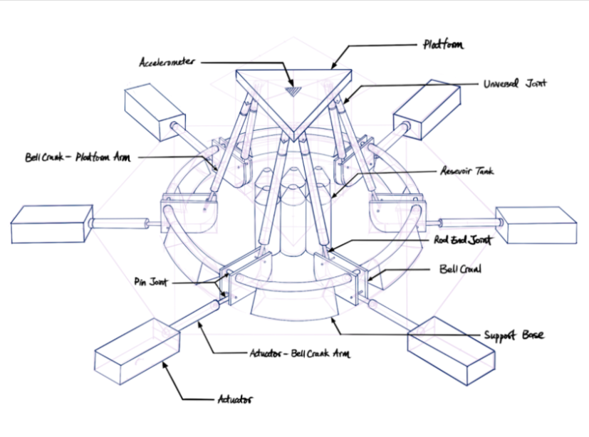
To do this — I first made a basic line-model (3D sketch in Solidworks) that represented our platform kinematics. This helped verify that the architecture does achieve our motion characteristics and I could see how different parameters affect things.
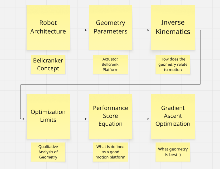
There were a lot of good learnings from messing around with this model, and I made some qualitative changes to make it more feasible in real life, but since the kinematics are very unintuitive, I was going to have to find a better way to optimize the geometry. So I came up with the following plan:
Parameter space
I first categorized the design into the parameters that we felt would most affect performance:
- Platform Parameters
- Platform Size
- Platform Arm (Pushrod) Lengths
- Bellcrank Parameters
- Actuator Lever Arm and angle from pivot
- Pushrod Lever Arm and angle from pivot
- Bellcrank Pivot locations (relative to robot center) r_b
- Bellcrank Pivot height off the ground
- Actuator Parameters:
- Actuator layout angles
- Actuator pivot locations (relative to robot center)
- Actuator pivot height off the ground
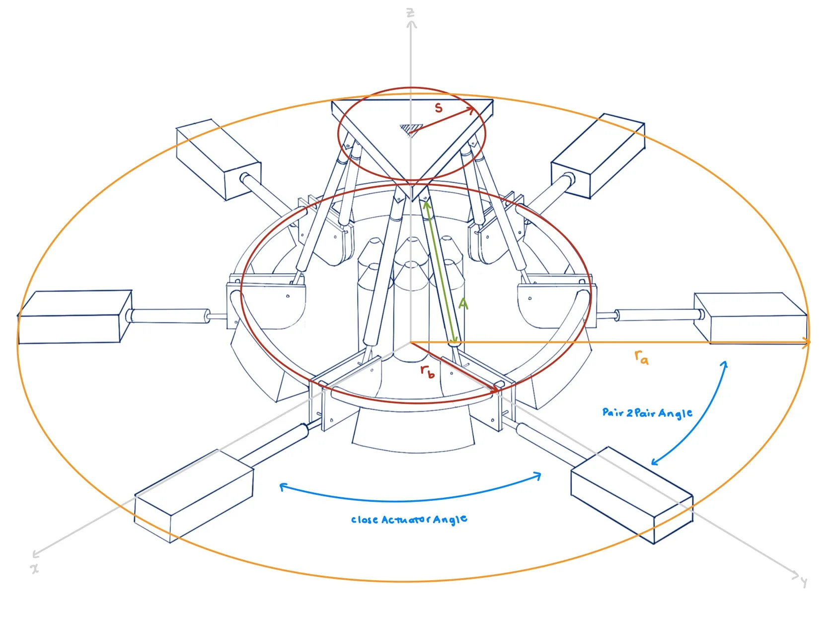
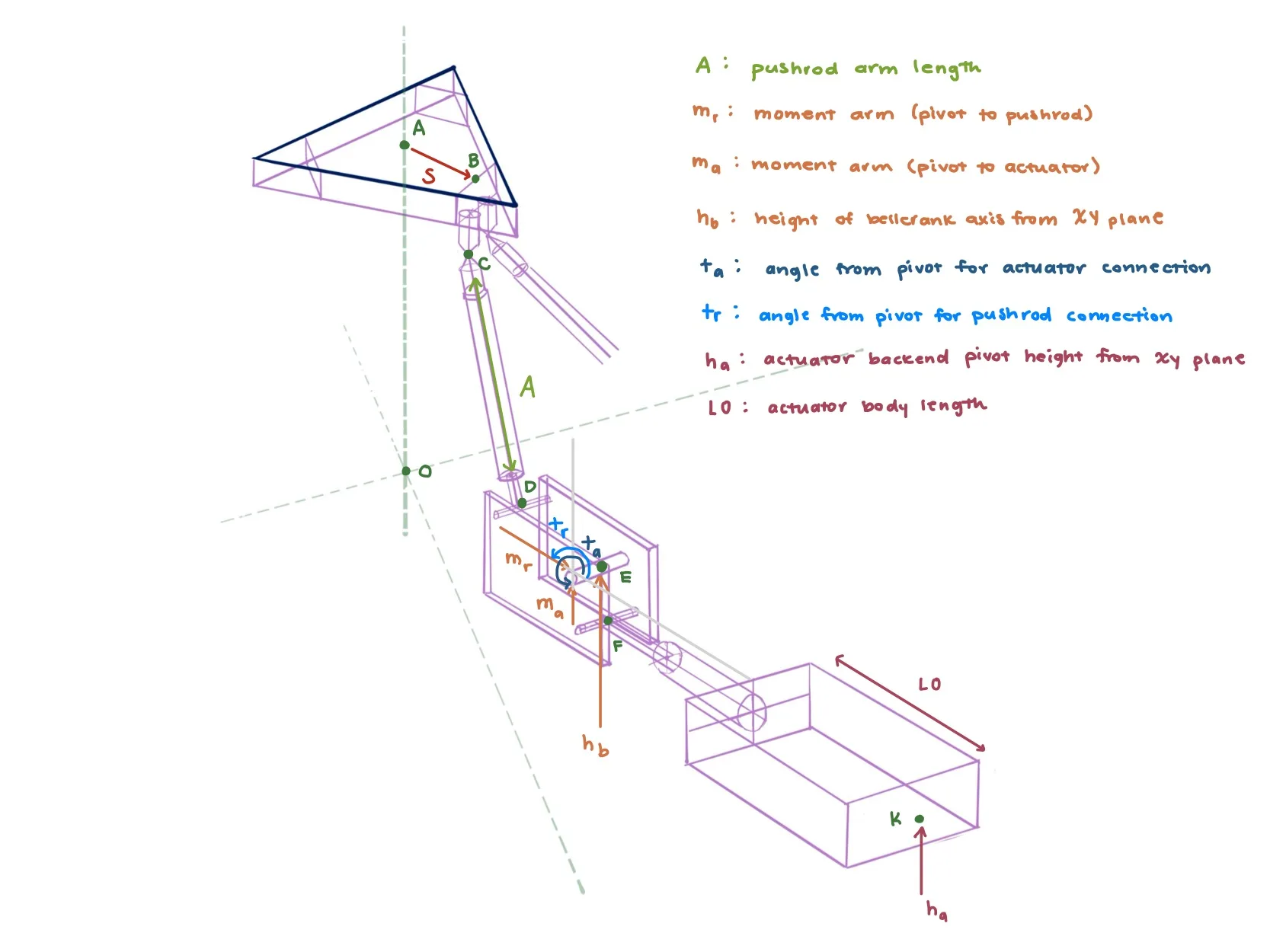
As you can see, this is a lot of parameters to keep track of (and actually there are even more) — so I then started doing some qualitative analysis to figure out which parameters:
- Don't impact performance much
- Can be derived from other parameters
- Can be simplified
- Can be optimized qualitatively / intuitively / are already determined by requirements
After all that — I landed up on 5 independent parameters to optimize:
- Platform size
- Pushrod Length
- Both Bellcrank Lever arms
- Bellcrank Pivot Location
Inverse kinematics & workspace
Next, I used the parameters to find the inverse kinematic equations that govern the motion of the robot. Inverse kinematics tells you: If I want my platform to go to X position and be in X orientation, what do my actuators need to do. This requires a lot of linear algebra and vectors, but it allows us to produce pretty graphs like this: representing the useful workspace of the system (All the positions and orientations the robot can physically reach)
This code has to be computed at a bunch of different platform orientations (roll, pitch, yaw), so this was very computationally intensive. I used an empty computer lab to divide the work across 5 different computers, and the MATLAB code ran parallel FOR-loops to take advantage of all the CPU cores of each computer.
* Note — I also used the Jacobian of the robot to cut off the workspace at points where the robot reaches a singularityA point where the robot loses all its strength in a certain direction. You want to avoid these points at all costs.
Coarse-search optimization
After all of this, I wrote a big coarse-search optimizer in MATLAB from scratch, checking 25 million parameter combinations and scoring them according to some specific performance criteria. This helped find the most optimal sizes of all our components in order to meet all our requirements and maximize performance!
For each of the 25 million parameters, I checked 3 different conditions at 12 different poses. This took a LOT of code optimization to make run fast enough. I used a bunch of tricks like parallel computing and early-exit for-loops to reduce the running time from weeks to just a few hours.
Next was to actually design the whole thing and source all the components, incorporating Design for Manufacturing and Assembly (DFM & DFA) principles. This is presented in the mechanical design section.