Why a full redesign
The previous year's pedal system failed at the competition. The root cause was an overengineered design — too many parts that were difficult to machine and assemble correctly, which meant it was never adequately tested before being run on the car. The consequence was a catastrophic failure, where part of the pedal base sheared off.
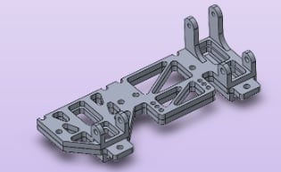
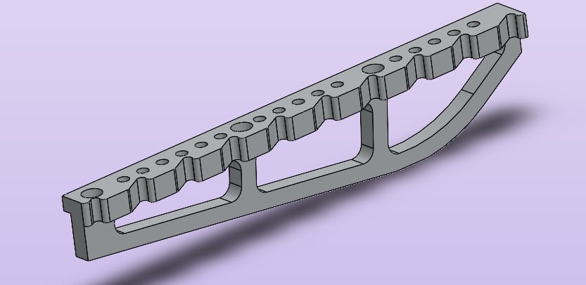
The components below were representative of the problem — complex geometry that was very difficult to machine reliably.
Designing from the ground up
I went into the design phase from first principles — starting with needs and requirements. The primary evaluation criteria were reliability, manufacturability and ease of assembly. And since it's a race car, any weight savings were welcome too.
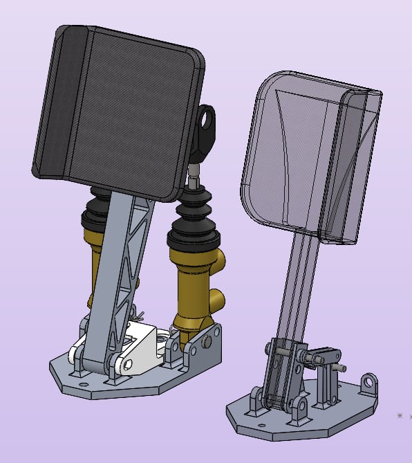
I began by removing every part that wasn't strictly necessary — reducing part count directly reduces the number of failure points. Wherever possible, I integrated multiple functions into a single part. This demanded some intensive CNC machining to achieve the features, so I optimized each design for manufacturing to make it easier.
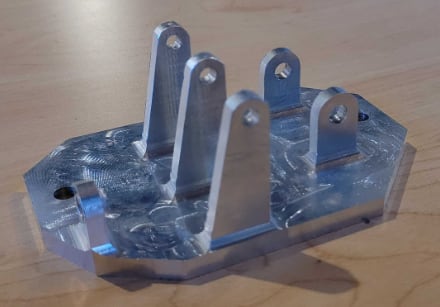
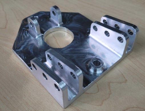
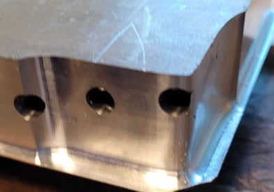
I also split the previously single pedal base into two separate bases, cutting overall weight, machining complexity and the amount of stock material needed. Both bases were machined mostly with one tool and one setup — only needing a second setup to drill the side holes.
Throttle linkage & easy assembly
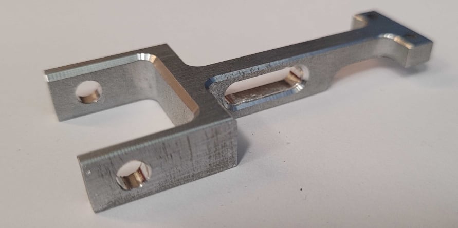
The throttle system had far more functions to fulfill than the brake side. One of my favorite parts — the throttle stop — achieves three of them in a single component. It attaches to the pedal, and a slot that rides along a pin acts as both a positive and negative throttle stop. It also carries the holes for the return springs that bring the throttle back to its zero position. This part needed to be manually machined, which was also very fun.
For the throttle, I used a linkage-based design to amplify the pedal's motion and pull a throttle cable with as little play as possible. I sourced press-fit pins and bushings off the shelf and designed my linkage geometry around them.
Throughout the assembly I used clevis pins and cotter pins instead of the bolts and nylon lock-nuts we'd relied on in previous years — a big contributor to ease of assembly.
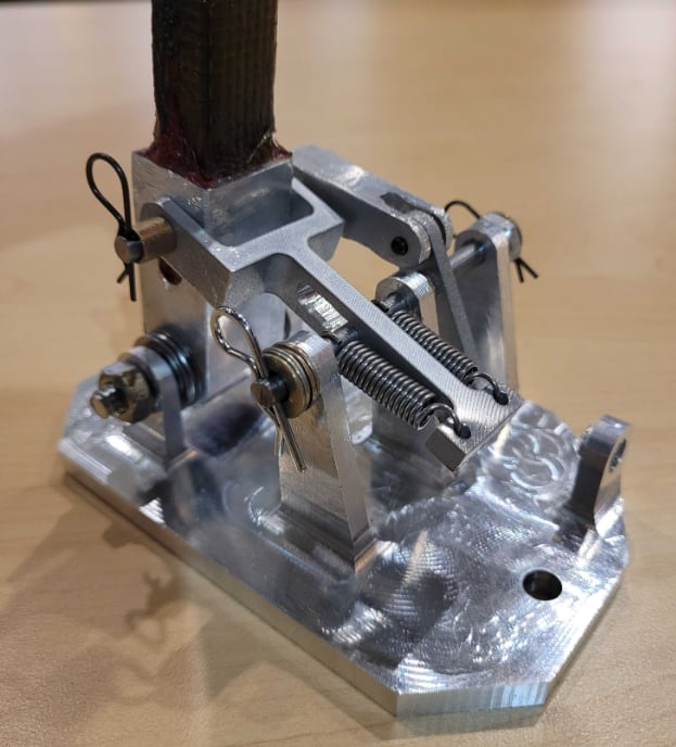
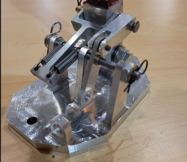
Assembly and disassembly became dramatically easier with so many fewer parts and fasteners. I designed the system so an impact wrench could drive every bolt — the whole pedal box can be removed in under 2 minutes if done right, staggeringly quick compared to the year before. As a co-benefit, we no longer have to work in the cramped cockpit: for changes or quick repairs we just pull the whole assembly out, avoiding the many cuts we used to get wrenching inside the car.
Validation & real-world testing
We didn't move to manufacturing until each design was verified with FEA — but a big goal of mine was to validate everything with real-world testing. This started as early as possible on the brake pedal base, using a mock-up carbon fiber floor model from our frame & body sub-team. We installed the brake pedal base and a to-scale mock pedal, strapped it all to a table, and had our strongest drivers stomp on it as hard as they could.
This not only simulated our highest load case but also tested fatigue reliability over 200+ load cycles. It was meant to be a destructive test — but nothing failed, which was a very pleasant discovery.
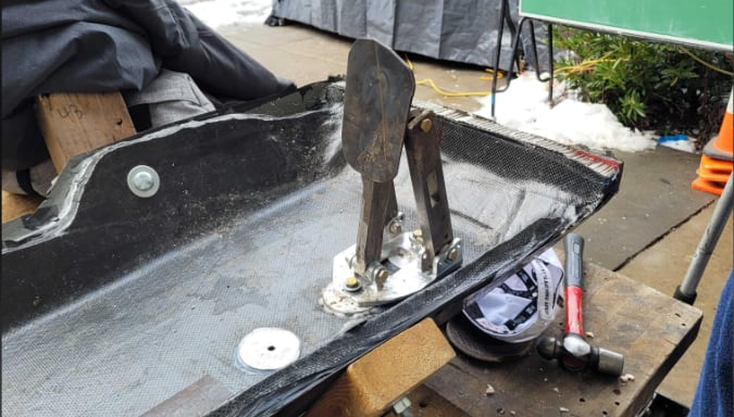
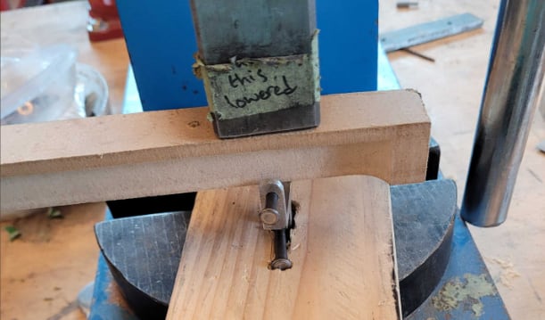
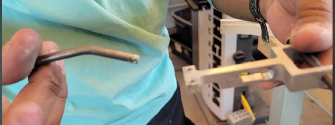
Similar tests were run on the final throttle and brake assembly in the car, asking drivers to be as rough as possible. Out of curiosity, I wanted to find the failure mode of the throttle stop if the load kept increasing, so I simulated the load case with an arbor press and a wooden block. I found that the off-the-shelf pins started yielding well before the throttle stop broke — which I was glad about, because those pins are a very easy part to replace and the failure is a slow, detectable one. If I ever needed a higher maximum load, I could simply source a higher-carbon-steel variant of the pins.
Results
Compared to the previous year's version, the brake and throttle pedal assembly I designed:
It's optimized for manufacturability and — most importantly — validated with real-world testing.
Hiccups & what I learned
As with any project, there were plenty of hiccups along the way — and it would be disingenuous not to mention them, because those were the learning opportunities that got me here.
- While learning to CNC machine, several mistakes with part setups and toolpaths meant multiple parts had to be remachined. Luckily, we have a basically unlimited supply of aluminum billet, so I could always learn from a mistake and improve on the next try — I now know infinitely more about CNC machining than when I started.
- The throttle system went through several design iterations, driven by evolving requirements from interfacing sub-teams and by issues — like tolerances and fits — that CAD didn't reveal.
All in all, I probably remade each part in the system at least once. But it was always far quicker the second time around, and it gave me a much deeper understanding of every detail of the assembly. I've formed an intuition about tolerance stack-upThe accumulation of individual part tolerances across an assembly, which determines whether mating parts actually fit and function together as intended. and fit design that will be invaluable in future projects.
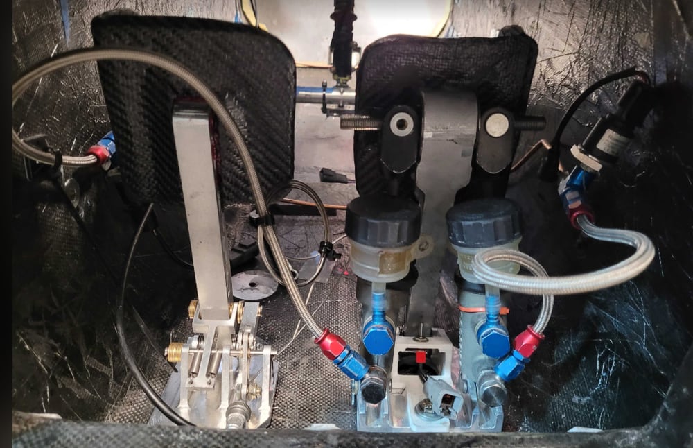
Between my own efforts and the feedback and guidance from everyone on the team, the pedal box reached a state far more reliable than in previous years. Outside of small improvements, we intend to keep using this design for a while. :)