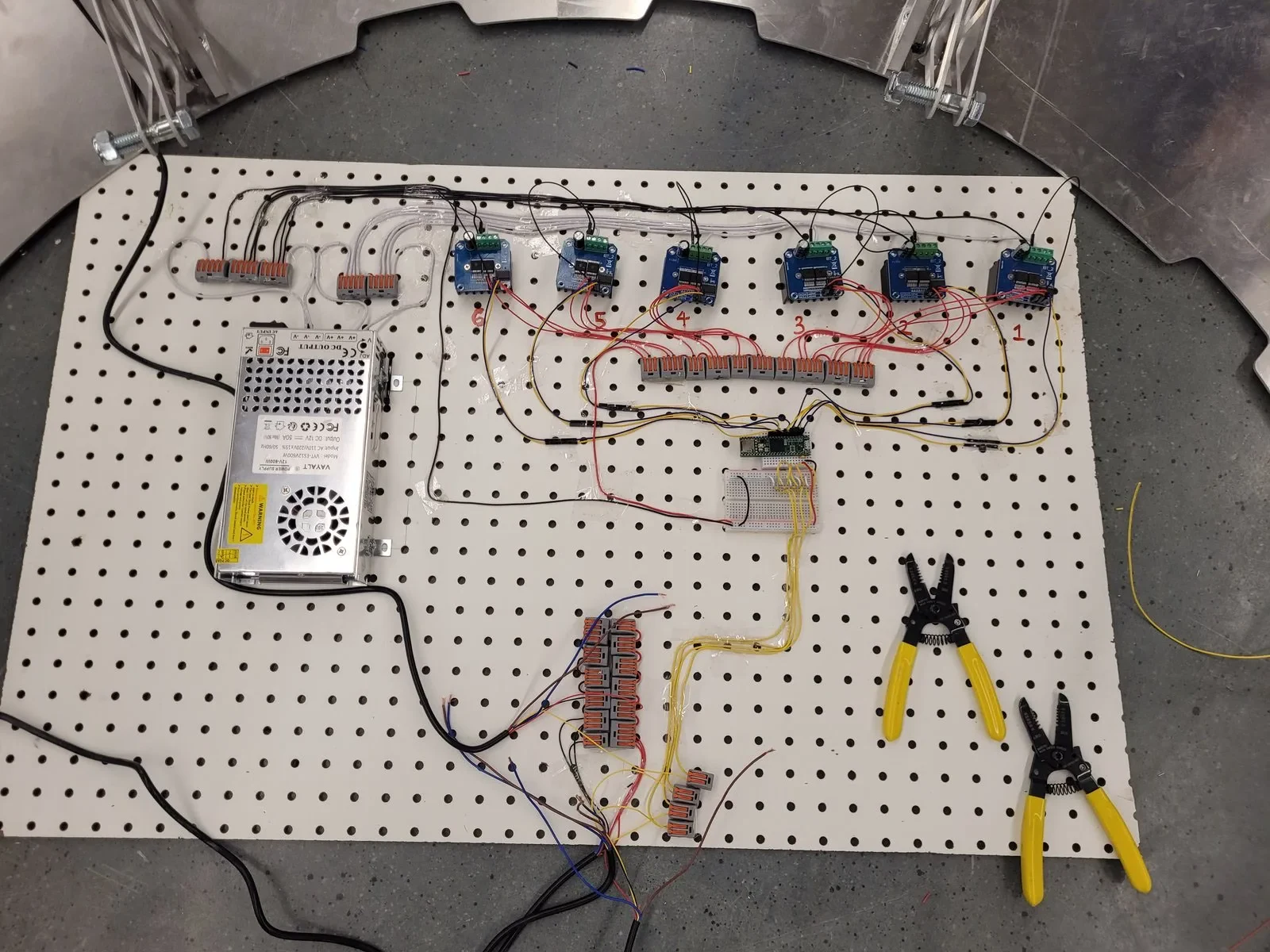
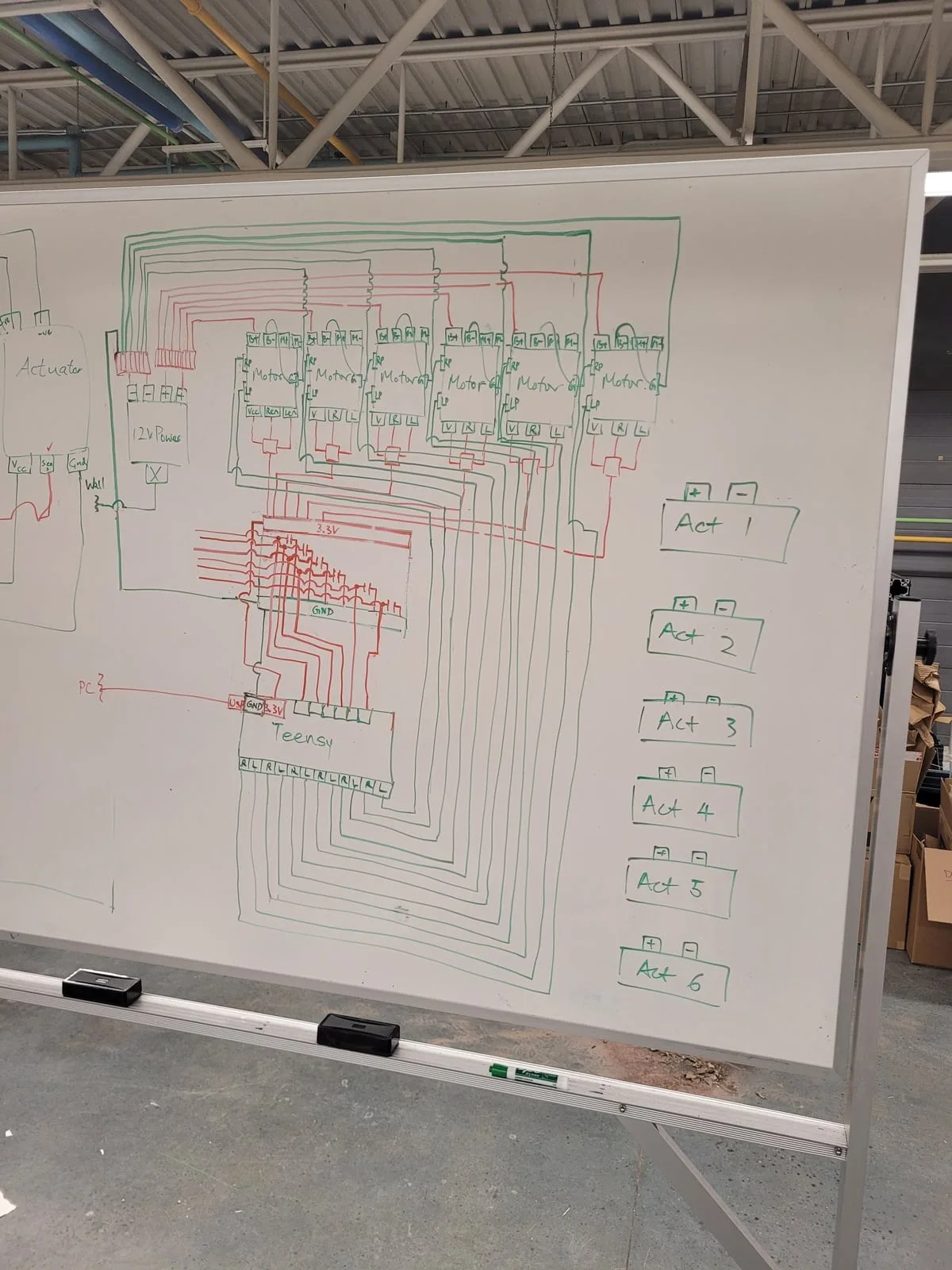
Controls board
PIV control loop
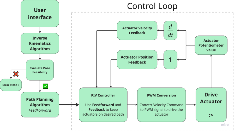
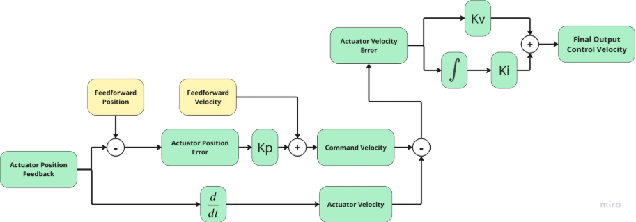
The controller uses a Proportional-Integral-Velocity (PIV)A control architecture with an explicit velocity feedback loop nested inside the position loop. Widely used in industry for motor control due to intuitive tuning and low steady-state error. control loop to regulate the motion of each actuator. PIV loops are commonly used in industry for motor control, due to their intuitive tuning process, low steady state error and fast response.
A PIV loop uses a Proportional gain for position error, and a Proportional-Integral architecture for velocity errors. By implementing the implicit velocity loop, the controller very closely follows the feed-forward path that the path planning algorithm generated. Through also implementing the position feedback, we can minimize our steady state error. With our tuning, I achieved a ±0.3 mm max steady state error for each actuator.
Path planning
To ensure smooth platform motion, we have to enforce a few rules for each actuator:
- All actuators must reach their target position in the same amount of time, regardless of travel distance
- All actuators must travel at or slower than their hardware limited max speed
- All actuators must travel at or slower than their hardware limited max acceleration
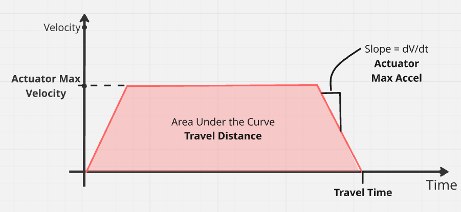
To achieve these rules, I implemented a path planning algorithm that is easily configurable and scalable to match our actuators. The velocity path looks like a simple trapezoid as shown below. The actuators linearly accelerate to some max velocity, stay at the max velocity for a set amount of time, and decelerate linearly to 0. The area under the trapezoid is the travel distance, and the total length of the trapezoid is the travel time.
To ensure all actuators have the same travel time, we simply scale the velocity path of some actuators down (effectively de-rating their velocity) so that they take the same amount of time as the actuator with the longest path. This is demonstrated in the right figure below, where:
- The yellow trapezoid is the longest-time actuator
- The blue trapezoid takes half the time as yellow, and thus gets scaled down into the pink trapezoid
- The pink trapezoid travels the same distance as the blue, in the same time as the yellow
- A similar process is done for the green triangle getting scaled down to the purple triangle
The trapezoidal paths are then fed forward to the controller, keeping the actuators on track.
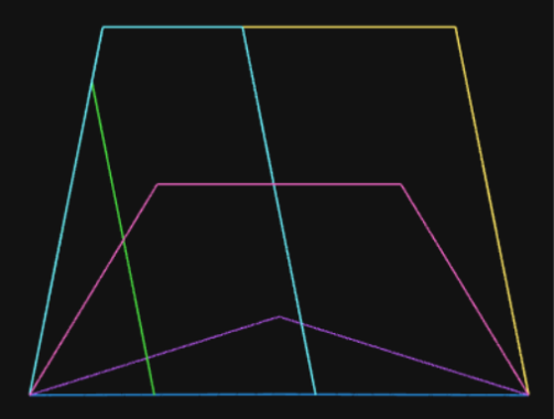
Velocity (y-axis) vs time (x-axis) — trapezoidal profile (left) and actuator path scaling for synchronisation (right)
Electronics